Day 5: Day 5:- RGB LED Color Mixing | 60-Day Arduino Course
1
2 const int redPin = 9 ;
3 const int greenPin = 10 ;
4 const int bluePin = 11 ;
5
6 void setup ( ) {
7 pinMode ( redPin , OUTPUT ) ;
8 pinMode ( greenPin , OUTPUT ) ;
9 pinMode ( bluePin , OUTPUT ) ;
10 }
11
12 void loop ( ) {
13
14 // Red
15 analogWrite ( redPin , 255 ) ;
16 analogWrite ( greenPin , 0 ) ;
17 analogWrite ( bluePin , 0 ) ;
18 delay ( 1000 ) ;
19
20 // Green
21 analogWrite ( redPin , 0 ) ;
22 analogWrite ( greenPin , 255 ) ;
23 analogWrite ( bluePin , 0 ) ;
24 delay ( 1000 ) ;
25
26 // Blue
27 analogWrite ( redPin , 0 ) ;
28 analogWrite ( greenPin , 0 ) ;
29 analogWrite ( bluePin , 255 ) ;
30 delay ( 1000 ) ;
31
32 // Yellow
33 analogWrite ( redPin , 255 ) ;
34 analogWrite ( greenPin , 255 ) ;
35 analogWrite ( bluePin , 0 ) ;
36 delay ( 1000 ) ;
37
38 // Purple
39 analogWrite ( redPin , 255 ) ;
40 analogWrite ( greenPin , 0 ) ;
41 analogWrite ( bluePin , 255 ) ;
42 delay ( 1000 ) ;
43
44 // Cyan
45 analogWrite ( redPin , 0 ) ;
46 analogWrite ( greenPin , 255 ) ;
47 analogWrite ( bluePin , 255 ) ;
48 delay ( 1000 ) ;
49
50 // White
51 analogWrite ( redPin , 255 ) ;
52 analogWrite ( greenPin , 255 ) ;
53 analogWrite ( bluePin , 255 ) ;
54 delay ( 1000 ) ;
55 }
56
57 Day 5 Core Training Documentation
The RGB LED Color Mixing project introduces one of the most exciting concepts in electronics: creating multiple colors using a single LED.
Unlike a standard LED that can only produce one color, an RGB LED contains three individual LEDs inside a single package:
By controlling the brightness of each color channel independently using PWM (Pulse Width Modulation), Arduino can mix these colors together to generate a wide variety of colors.
This project introduces:
RGB Color Mixing
Pulse Width Modulation (PWM)
Multiple Output Control
Analog Brightness Adjustment
Color Generation Techniques
By the end of this project, you'll understand how displays, LEDs, and smart lighting systems create millions of colors.
Arduino Uno × 1
Breadboard × 1
RGB LED × 1
Step 1: Connect Ground Rail Connect the Arduino GND pin to the negative rail of the breadboard.
This provides a common ground reference for the RGB LED.
Step 2: Place the RGB LED Insert the RGB LED into the breadboard.
Ensure all four legs are placed in separate rows.
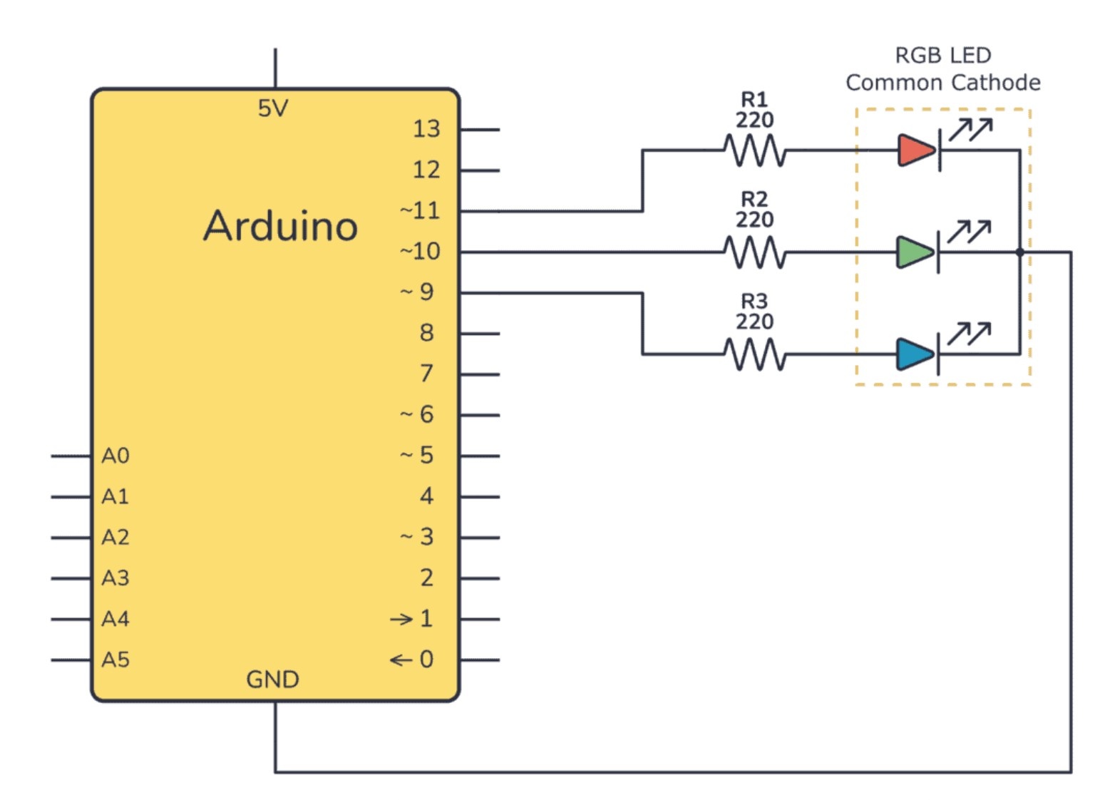
Step 3: Connect the Red Channel Connect the Red pin of the RGB LED to Arduino Pin 9 through a 220Ω resistor.
Step 4: Connect the Green Channel Connect the Green pin of the RGB LED to Arduino Pin 10 through a 220Ω resistor.
Step 5: Connect the Blue Channel Connect the Blue pin of the RGB LED to Arduino Pin 11 through a 220Ω resistor.
Step 6: Connect the Common Pin Connect the longest leg (Common Cathode) of the RGB LED directly to the breadboard ground rail.
Step 7: Verify Connections Check all resistor connections and verify that the RGB LED pins are connected to the correct Arduino pins.
Important: This project assumes a Common Cathode RGB LED. If you are using a Common Anode RGB LED, the code logic must be inverted.
Configure Output Pins Inside setup(), Arduino configures Pin 9, Pin 10, and Pin 11 as output pins.
Each pin controls one color channel of the RGB LED.
Generate Individual Colors Using analogWrite(), Arduino controls the brightness of:
Red Channel
Green Channel
Blue Channel
Each channel accepts PWM values between 0 and 255.
Create Color Mixing Different combinations of Red, Green, and Blue produce different colors.
Red + Green + Blue = White
Control Brightness PWM allows Arduino to control how bright each color channel appears.
By changing brightness levels, millions of unique color combinations can be created.
After uploading the code:
RGB LED displays Red
RGB LED displays Green
RGB LED displays Blue
RGB LED displays Yellow
RGB LED displays Purple
RGB LED displays Cyan
RGB LED displays White
The sequence repeats continuously.
RGB LED Does Not Light Up: Verify the common pin connection and check LED orientation.
Incorrect Colors Appear: Check the wiring of the Red, Green, and Blue pins. Some RGB LEDs use a different pin order.
Only One Color Works: Verify all resistor connections and PWM pin assignments.
Upload Errors: Confirm the correct board and COM port are selected in Arduino IDE.
By completing this project, you have learned:
How RGB LEDs work
How PWM controls LED brightness
How color mixing works
How multiple outputs can be controlled simultaneously
How modern lighting systems generate colors
In Day 6 , you'll build an Arduino Traffic Light System and learn how multiple LEDs can be controlled using timing logic and sequencing techniques.
Breadboard
Male to male jumper wires