Welcome to Day 4 of your core electronics training! In previous modules, your microcontroller operations were strictly binary: an LED could only be completely ON or completely OFF. Today, we break out of those digital boundaries and explore how to simulate intermediate analog states to smoothly control an LED's brightness, creating a professional "breathing" or fading effect.
📋 Project Overview
The PWM LED Brightness Control project introduces one of the most critical concepts in embedded engineering: Pulse Width Modulation (PWM). Instead of changing the actual physical voltage output, the Arduino flips a digital pin between HIGH and LOW states at an incredibly high frequency. By varying the ratio of time the signal spends in the HIGH state vs. the LOW state, we control the average power delivered to the component.
🧠 Core Concepts Covered
Simulating analog voltage levels using high-frequency digital switching.
Day 4: Day 4:- PWM LED Brightness Control | 60-Day Arduino Course
Pulse Width Modulation (PWM):
Analog Output Simulation: Utilizing analogWrite() to map a digital value sequence into a smooth power curve.
Iterative Logic Structures: Deploying for loops to scale values smoothly over time.
Variable-Based Control: Binding hardware output pins to dynamic programming variables.
🛠️ Components Required
| Component | Quantity | Purpose |
| :--- | :---: | :--- |
| Arduino Uno | 1 | Master microprocessing unit |
| Breadboard | 1 | Solderless prototyping workspace |
| LED (Any Color) | 1 | Visual output target |
| 220Ω Resistor | 1 | Current limiting protection for the LED |
| Jumper Wires | 2 | Inter-component electrical bridges |
| USB Cable | 1 | Power supply and IDE program transfer |
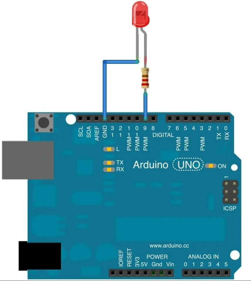
🔌 Circuit Connections
Follow these steps carefully to assemble your hardware layout on the breadboard workspace:
🧩 Step 1: Establish the Common Ground
Connect one jumper wire from the GND pin on your Arduino to the negative (-) rail of your breadboard. This establishes a universal ground plane for the circuit.
🧩 Step 2: Wire the LED Array
Insert your LED pins cleanly into separate tracks on the breadboard:
Long Leg (Anode / +): Connect this leg to Digital Pin 9 on the Arduino through your 220Ω resistor.
Short Leg (Cathode / -): Connect this leg directly to your negative breadboard ground rail.
🧩 Step 3: Pre-Power Inspection
Double-check your LED orientation (polarity) and verify your resistor legs aren't accidentally crossing neighboring tracks before connecting your USB controller cable.
⚠️ Critical Hardware Note: PWM signals cannot be generated from just any digital pin. On the Arduino Uno, hardware PWM registers are hardwired exclusively to pins marked with a tilde symbol (~): Pin 3, 5, 6, 9, 10, and 11.
⚙️ How the Arduino Code Works
🎛️ 1. Configure the Output Pin
Inside setup(), Arduino configures Pin 9 as an output source (OUTPUT). This tells the board's internal logic matrix to prepare the pin for driving hardware currents to the external LED link.
📈 2. The Fade-In Phase
The first for loop gradually increases the brightness variable value from 0 to 255. As the value scales upward, the average voltage delivered to the pin rises, forcing the LED to grow increasingly brighter at an incremental rate.
📉 3. The Fade-Out Phase
The second for loop executes the reverse logic loop. It gradually decreases the variable from 255 down to 0. As the numeric input parameters scale down, the power delivery cycle drops, causing the LED to smoothly dim.
🔄 4. Managing 8-Bit PWM Resolutions
The analogWrite() command feeds an integer byte directly into the Arduino's internal 8-bit timer registers. This scales your output control into an exact resolution window spanning 0 to 255:
128 $\rightarrow$ 50% Duty Cycle: The pin pulses evenly (LED glows at approx. 50% brightness).
255 $\rightarrow$ 100% Duty Cycle: The pin stays permanently HIGH (LED glows at maximum brightness).
👁️ Expected Output
After uploading the script module to your hardware stack, you will witness the following behavior:
The LED will cleanly fade from an absolute dead state (OFF) up to its highest possible illumination point (100% Brightness).
Once it hits the peak, it will reverse seamlessly and fade from full visibility back down to zero.
This process continues to cycle sequentially, creating a fluid, professional breathing lighting effect.
🛠️ Operational Troubleshooting
💡 LED Switches ON/OFF Abruptly (No Fading): Pin Assignment Error. Ensure your jump wire routes strictly into Pin 9. Standard digital pins cannot process intermediate PWM duty cycles and will treat any non-zero value as a hard 100% HIGH switch.
💡 LED Remains Completely Dead: Polarity Mismatch. Unplug your USB power cable, turn your LED exactly 180° to flip the anode and cathode channels, re-insert the legs, and inspect for broken track links.
💡 Fading Changes Are Not Smooth: Loop Timing Issue. Check the parameter values inside your delay() trackers. Decreasing the delay value accelerates the breathing sequence, while increasing it lengthens the transition time.
💡 Arduino IDE Upload Errors: Port/Board Timeout. Open the Tools dropdown panel menu in your desktop IDE to guarantee your active microcontroller target points to Arduino Uno over an active, un-shared COM communication port.
🎓 Summary: What You Learned Today
The Physics of Pulse Width Modulation: Modulating electrical current flow using automated duty-cycle square waves.
Deploying 8-Bit Controllers: Interfacing with hardwired hardware registers ranging from 0 up to 255.
Symmetrical Program Flows: Nesting incremental and decremental mathematical loops within unified program loops.
🚀 Next Lesson Preview
In Day 5, we take this exact multi-level PWM engine and scale it across a unified RGB LED module, mastering individual color spectrum variables to generate thousands of custom colors from a single hardware workspace!