The Button Controlled LED project introduces one of the most fundamental design concepts in embedded systems: Digital Inputs. In this guide, a physical tactile push button connected to Pin 2 is monitored to control an LED linked to Pin 13 dynamically.
When the tactile button is pressed, the Arduino detects a voltage transition state and turns the LED ON. Releasing the button breaks the channel, automatically turning the LED OFF.
This lesson explores several key hardware and programming architectures:
Digital Inputs: Reading discrete logic signals from external interactive components.
Push Button Interfacing: Connecting tactile switches to a microcontroller input line.
Input/Output Interaction: Writing control logic to change physical outputs based on user interaction states.
Serial Monitoring: Streaming real-time hardware values back to your computer console.
To build this circuit, collect these specific items from your kit:
Arduino Uno MCU Board × 1
Solderless Prototyping Breadboard × 1
5mm Vivid LED × 1
Tactile Push Button Switch × 1
220Ω Current-Limiting Resistor × 1
Solid-Core Jumper Wires × 4
Type-B USB Cable × 1
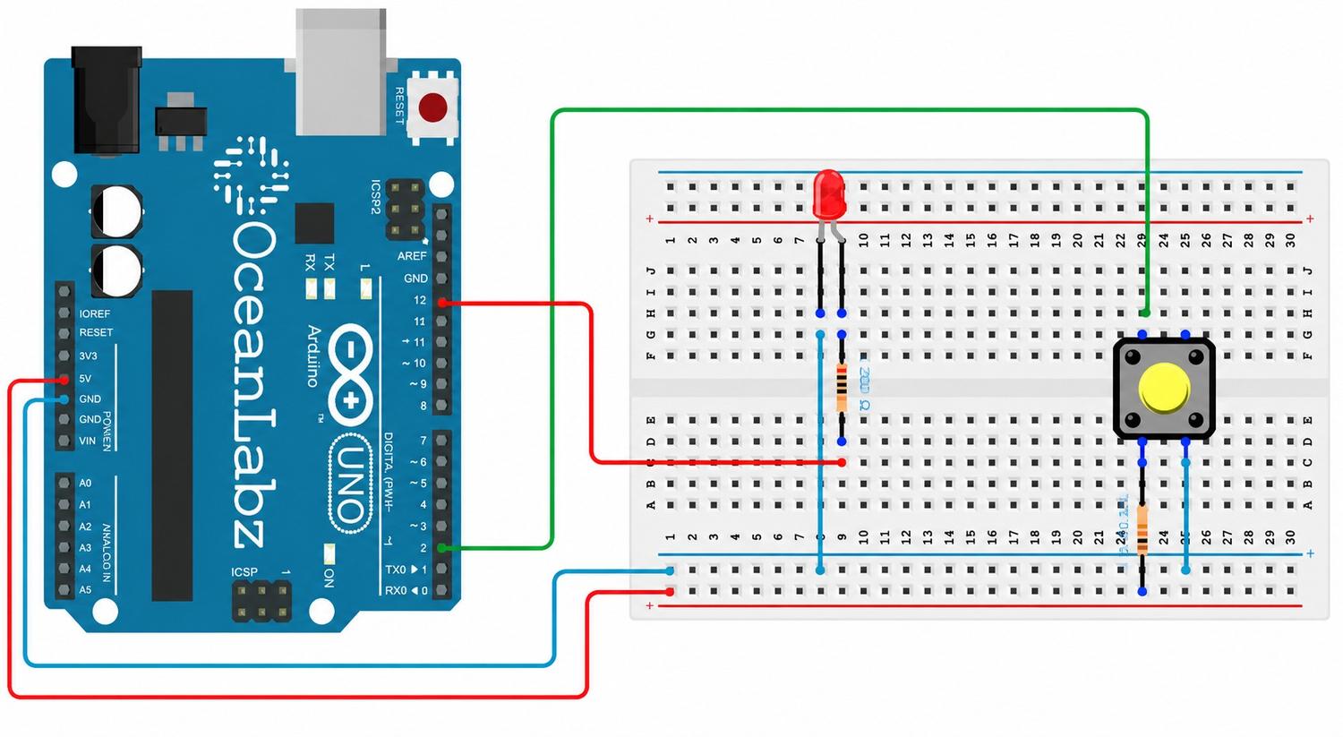
Circuit Connections
Step 1: Establish the Common Ground
Run a jumper wire from an Arduino GND pin directly onto the long blue negative rail (-) of your breadboard. This sets up a unified reference voltage plane for the loop.
Step 2: Wire the LED Output Channel
Insert your LED into two separate breadboard rows.
Connect the long leg Anode (+) to Arduino digital Pin 13 through your 220Ω protective resistor.
Connect the short leg Cathode (-) directly over to the negative ground rail line.
Step 3: Integrate the Push Button
Place the tactile push button across the center isolation trench of your breadboard.
Connect one pin on the button directly to Arduino digital Pin 2.
Connect the diagonally opposite pin of the button to the negative ground rail line.
Push Button Warning: Always position the push button across the center split trench of the breadboard. Incorrect placement on a single horizontal row can bridge both terminals together permanently, shorting the circuit path and preventing the microcontroller from reading changes.
Step 4: Final Inspection
Verify that your signaling wires run to Pin 13 and Pin 2 cleanly, and ensure all ground connections return to the breadboard's common negative rail layer.
How the Arduino Code Works
Configure Pin Operating Modes
Inside your initialization function setup(), the Arduino sets up the I/O configurations:
Pin 13 is set as an OUTPUT to drive current out to the LED.
Pin 2 is set using INPUT_PULLUP mode.
The built-in internal pull-up resistor pulls the voltage level on Pin 2 up to a default stable HIGH (+5V) state when the button is open, completely removing the need for an external resistor.
Reading and Interpreting Hardware States
Inside your continuous runtime loop loop(), the Arduino tracks the button status via digitalRead(2):
Button Pressed: The switch closes, routing the signal path directly to GND. Pin 2 collapses to a LOW logic state (0V), instructing the Arduino to turn the LED on.
Button Released: The switch opens, breaking the path to ground. The internal pull-up pulls the channel back to a stable HIGH state (+5V), instructing the Arduino to turn the LED off.
Serial Monitor Feedback
The program simultaneously streams telemetry back to the computer console using Serial.println(). When the button is closed and reading a ground connection, it outputs a 1 to indicate an active trigger state. When released, it outputs a 0.
Expected Output
After successfully compiling and flashing your sketch to the board:
Pressing the push button down will instantly illuminate your LED.
Releasing the switch will instantly turn the LED off.
Opening your Serial Monitor console at a 9600 baud rate will display a real-time stream of 1 tags when pressed and 0 tags when released.
Operational Troubleshooting
LED Does Not Turn ON: If the button click path fails to trigger the light source, verify your output wiring lines. Check the LED polarity layout orientation, check that your current resistor is seated cleanly on the correct lines, and ensure your signal wire runs to Pin 13.
Push Button Not Responding: If your input clicks register no changes, check your button orientation. Ensure the switch bridges the center gap cleanly and confirm that one side routes down to a GND node while the other terminates at Pin 2.
Serial Monitor Shows No Values: If your terminal screen remains blank, check your initialization blocks. Confirm that your code executes Serial.begin(9600); inside setup(), and verify that the bottom-right dropdown value inside your IDE Serial Monitor window matches 9600 baud.
LED Remains ON Continuously: If your LED light source is activated immediately before you touch the button, this indicates an unexpected circuit bridge or missing software rules. Double-check that you configured INPUT_PULLUP correctly in your setup block rather than standard INPUT.
What You Learned
By completing your second micro-processing laboratory project, you have mastered:
How to properly interface and wire a tactile push button switch block.
How an Arduino reads discrete digital input frequencies.
How to build interactive loops that link output actuators to user inputs.
How INPUT_PULLUP simplifies hardware schematics by activating internal chip components.
How to track and print diagnostic execution data using the Serial Monitor console.
Next Lesson
In Day 3, you will learn how to turn a basic momentary push button into a true toggle switch! We will look at how to store previous states inside software memory variables, where a single click leaves the LED fully on and a subsequent click turns it off.