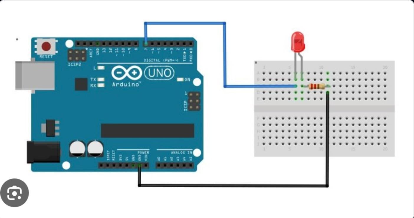
The Blinking LED project is the traditional starting point for learning microcontrollers. In this guide, an LED connected to Pin 13 repeatedly cycles its state between HIGH (+5V) and LOW (0V) at a fixed 1-second interval.
This foundational lesson introduces core embedded hardware concepts:
Digital Outputs: Sending discrete voltage signals from microcontroller pins.
Arduino Programming Structure: Understanding the setup routine vs. the execution loop.
To build this circuit, collect these specific items from your kit:
Arduino Uno MCU Board × 1
Solderless Prototyping Breadboard × 1
5mm Vivid LED × 1
220Ω Current-Limiting Resistor × 1
Solid-Core Jumper Wires × 2
Type-B USB Cable × 1
Circuit Connections
Step 1: Connect Ground Rail
Run a jumper wire from an Arduino GND pin directly onto the long negative rail (-) of your breadboard. This creates a common ground connection for the entire circuit loop.
Step 2: Connect the LED
Insert your LED legs into two separate rows on the breadboard layout canvas.
Connect the long leg Anode (+) to Arduino digital Pin 13 through your 220Ω protective resistor.
Connect the short leg Cathode (-) directly over to the negative ground rail line.
Step 3: Verify Connections
Double-check all wire positions before powering the board. The completed circuit should allow the Arduino to safely control voltage delivery straight to Pin 13.
Polarity Warning: Diodes are unidirectional valves for current! Ensure the LED polarity is correct. Reversing the LED legs will prevent current from flowing, meaning it will not light up.
How the Arduino Code Works
Configure the Output Pin
Inside the initialization block setup(), the Arduino configures Pin 13 as an output. This drops internal resistance, allowing the board to send voltage signals down the copper trace lines.
Turn the LED ON & OFF
Using digitalWrite(13, HIGH) supplies a full +5V voltage to the LED, causing it to light up immediately. Conversely, calling digitalWrite(13, LOW) removes the voltage, collapsing the channel down to 0V (GND) and turning the LED off.
Create the Blink Effect
The delay(1000) function pauses program execution for exactly 1000 milliseconds between state changes. Repeating these actions sequentially inside the infinite runtime loop loop() creates the blinking pattern.
Expected Output
After successfully compiling and uploading the sketch to your board:
The LED turns ON for 1 second.
The LED turns OFF for 1 second.
The process automatically repeats continuously.
Operational Troubleshooting
LED Does Not Turn ON: If the light stays completely dark, verify your component connections. Check the LED polarity orientation, resistor seat lines, and jumper wire connections. Most blinking LED issues occur because the LED legs are inserted in reverse.
Upload Failed Errors: If the compiler throws communications errors, verify your connection setup inside the Arduino IDE. Check that your USB cable supports data transfer, confirm the correct board model is selected under Tools, and make sure the correct active COM port is checked.
LED Stays ON Constantly: If your light remains completely illuminated without cycling, check your script logic. Ensure the correct blinking sketch was uploaded successfully and verify that delay() functions are present between both your high and low write states.
What You Learned
By completing your very first hardware experiment, you have mastered:
How to wire a discrete light-emitting diode with a microcontroller.
How digital outputs toggle power states.
How to reference and address static hardware pins like Pin 13.
How the main runtime engine executes loops sequentially.
Next Lesson
In Day 2, you will learn how to read digital inputs by integrating a tactile push button switch into your breadboard layout, using interactive user inputs to control your LED states dynamically!