The ESP32 Spider-Man Web Shooter project demonstrates an interactive, wearable Internet of Things (IoT) application combining real-time motion sensing, embedded audiovisual feedback, and bidirectional WebSocket communication.
In this project, an ESP32 microcontroller interfaces with an MPU6050 6-axis Inertial Measurement Unit (IMU) strapped to your wrist. When you perform the classic Spider-Man wrist snap gesture, the accelerometer registers the sharp spike in kinetic G-force magnitude. Instead of relying on external routers or cloud infrastructure, the ESP32 acts as a standalone Wi-Fi Access Point and local WebSocket Server, broadcasting instant triggers to an animated web dashboard.
By completing this project, you will understand how to process raw motion data from an IMU, interface hardware feedback peripherals, and push low-latency events to a live web interface without needing an internet connection.
Components Required
ESP32 DevKit V1 (30-Pin) × 1
MPU6050 Accelerometer & Gyroscope Module × 1
Active or Passive Buzzer × 1
5mm Red LED × 1
220Ω Resistor × 1
Half-Size or Mini Breadboard × 1
Male-to-Male Jumper Wires × 1 Set
Micro-USB or Type-C Cable × 1
Wrist Mount Strap or Velcro Band × 1
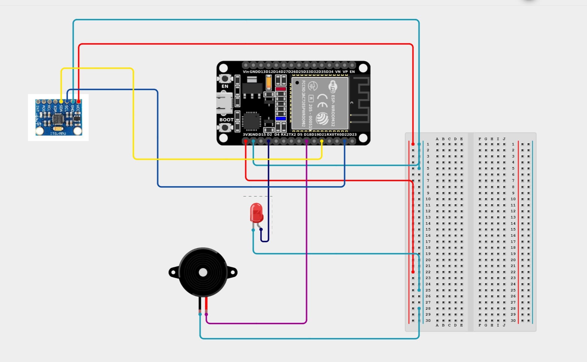
Circuit Connections
Design Note: Use flexible jumper wires and mount the components compactly on a half-size breadboard or wrist strap so your arm can move freely during gestures.
Step 1: Connect the MPU6050 IMU Module (I2C Bus)
Connect the MPU6050 sensor to the ESP32 I2C hardware bus:
VCC → ESP32 3V3(Important: Power using 3.3V to match logic levels)
GND → Breadboard GND Rail
SCL → ESP32 GPIO 22 (D22)
SDA → ESP32 GPIO 21 (D21)
Step 2: Connect the Status LED
Connect the trigger indicator LED with current-limiting protection:
Inside setup(), the ESP32 establishes a private local Wi-Fi hotspot (SpiderMan_Shooter) using WiFi.softAP(). It initializes an HTTP server on port 80 to serve the web application from index.h and starts a WebSocket server on port 81 for real-time messaging.
Sample Acceleration & Detect Gestures
Inside loop(), the ESP32 continuously polls the MPU6050 over the I2C bus at register 0x3B. It converts the 16-bit raw acceleration readings into G-forces across all three axes ($a_x$, $a_y$, $a_z$) and computes the total magnitude:
$$\text{Total G} = \sqrt{a_x^2 + a_y^2 + a_z^2}$$
Apply Trigger Filtering & Debouncing
When a sudden wrist flick or snap motion causes the G-force vector to exceed the preset trigger threshold (e.g., $> 2.20\text{ g}$), the firmware initiates the firing sequence and locks out further triggers for a cooldown period to prevent false multi-triggering.
Push Hardware Alerts & WebSocket Broadcast
After a calibrated 200 ms gesture settling delay, the ESP32 executes two simultaneous actions:
It broadcasts the text message "SHOOT" over WebSockets to all connected client browsers, immediately rendering a spider-web impact graphic and screen shake.
It turns ON the red LED and generates a continuous audio tone on the buzzer for 600 ms before returning to monitoring mode.
Expected Output
After uploading the code and powering the ESP32:
The buzzer emits a brief startup chirp to confirm hardware initialization.
The ESP32 broadcasts a Wi-Fi network named SpiderMan_Shooter.
Connecting your smartphone, tablet, or laptop to this network and navigating to http://192.168.4.1 opens the HUD dashboard displaying STATUS: CONNECTED.
Performing a sharp wrist flick gesture triggers a 200 ms pause, flashes the red LED, sounds the buzzer for 0.6 seconds, and spawns a spider-web impact graphic on your browser screen in real time.
Operational Troubleshooting
MPU Not Detected on 0x68: Check your SDA (D21) and SCL (D22) connections. Ensure the sensor's AD0 pin is connected to GND (or left floating) to keep its default I2C address at 0x68.
Buzzer Silent or Making Single Clicks: If using an active buzzer, drive the pin high using standard digital logic. If using a passive buzzer, ensure the frequency pulse function is toggling the pin. Move the buzzer from strapping pin GPIO 5 to clean PWM pin GPIO 18 if issues persist.
Web Dashboard Disconnected: Ensure your device remains connected to the SpiderMan_Shooter Wi-Fi Access Point and that cellular data is temporarily disabled so your browser routes traffic to 192.168.4.1.
False Triggers / Over-Sensitivity: Increase the BIG_MOVEMENT_THRESHOLD parameter in the firmware from 2.20 to 2.50 or higher to require a stronger, more deliberate wrist snap.
What You Learned
By completing this project, you have learned:
How to sample raw 3-axis accelerometer registers from the MPU6050 over I2C
How to calculate composite acceleration vectors for gesture recognition
How to run an independent SoftAP network and embedded HTTP web server on the ESP32
How to stream low-latency trigger events to browser clients using WebSockets
How to integrate synchronized audiovisual feedback into wearable maker projects
Next Lesson
In the next project, you'll learn how to build an IoT Environmental & Gas Monitor using an MQ-series sensor, Bluetooth Low Energy (BLE), and an asynchronous web dashboard.